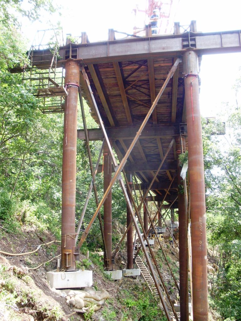
Work Trestle – Foothills Parkway Bridge No. 2 (PDF) –
This project required a temporary work trestle bridge to facilitate the top-down construction and erection of the Foothills Parkway Bridge No. 2, a precast balanced cantilever bridge in the Great Smoky Mountain National Park, Tennessee. The trestle was supported by precast pile caps sitting on drilled and grouted micro-piles. With a length of 790 ft / 240 m, this temporary access bridge had a grade of 7%. It closely followed the contour lines of the terrain, resulting in an S-shaped structure (reverse curve). As the trestle had to support several different types of major equipment, such as a conventional crane, trucks, forklifts and the segment gantry crane, the deck width and supporting beams had to be adjustable.
The trestle heading was used to construct the trestle foundations from the top down as trestle construction advanced along the mountain side. This was followed by the erection of the trestle columns and beams, again working from the already erected parts of the trestle. Simultaneously with the trestle erection, the permanent bridge foundations were also constructed from the trestle, again working from the top down. This top-down form of construction was required by contract to minimize any environmental disturbances at ground level. Thus no access roads had to be cut into the side of the mountain and much of the vegetation was spared from destruction.
Once the trestle was completed, a custom gantry crane was placed on top of it. Running on the trestle, this gantry crane carried the precast segments from the abutment to the point of erection. The gantry crane then matched the segments to the cantilever geometry, using hydraulic mechanisms for tilting the segment into the proper orientation i.e. matching the segment to the longitudinal and transverse slopes of the bridge. Segments were connected to the bridge with epoxy and temporary post-tensioning (PT) bars. At this point, the gantry crane could release the segment and move on. This was followed by the installation of the longitudinal bridge tendons and the subsequent removal of the temporary PT bars. Trestle removal occurred in reverse, again working from the top down.
CTE provided the overall design, layout, engineering, structural analysis and contract drawings for the trestle. We also developed very effective procedures for matching and installing the precast pile caps to the as-built micro-pile layouts. The pile caps were installed perfectly level. The column supports were designed to be interchangeable between fixed and pinned, to permit fine-tuning of the structural response to the various loading conditions.
