
![]()
![]()
![]()
![]()
![]()
![]()
![]()
![]()
![]()
![]()
![]()
![]()
![]()
![]()
| Buildings |
| Since 2006, CTE has also been offering structural engineering services for coastal properties, as well as for commercial and industrial buildings. |
| Near Westport, Massachusetts | |
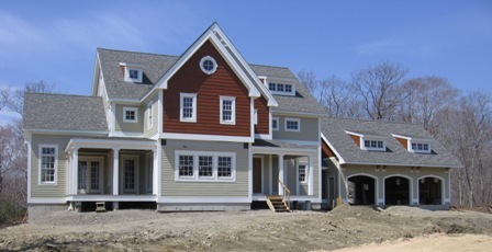 | On this project, CTE acted both as architect and engineer. This coastal structure was designed for high winds and included a high-performance tie-down system. Steep roof slopes and dormers minimize wind uplift that is so detrimental to flat gable and hip roofs. |
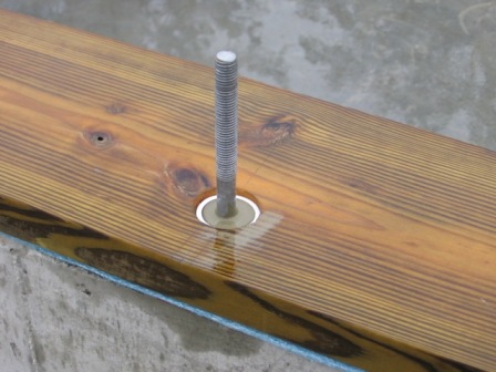 | During full scale testing in California, simulating only a moderate earthquake, a code-compliant house moved 4" to 5" off its foundation, resulting in repairs close to 100% of the building replacement cost. To prevent such an event, the anchor bolts were sleeved in 2" PVC pipe and 8000 psi grout to increase the bearing strength between bolt and sill plate by a factor of 3. |
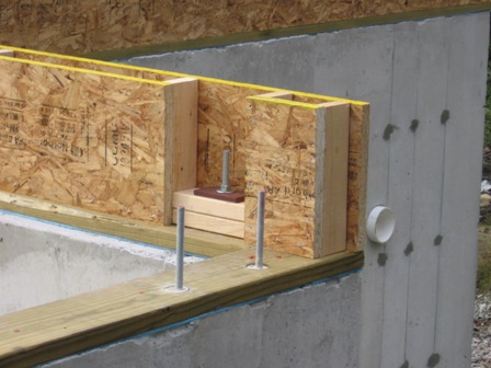 | Where the rim board runs parallel to the floor trusses, pockets were created to permit the installation of couplers for continuing the all-threads into the first-floor walls. Intermediate anchor plates were installed above the sill plate to create an additional load path for the exterior sheathing, through the sill plate and rim board. |
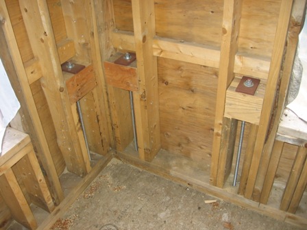 | Here the all-threads were extended into the first-floor walls, with the help of couplers. Cripple studs were nailed and screwed to king studs to transfer the loads from the walls to the tie-downs. This approach does require careful design and planning, since the all-threads are poured into the foundation and the framing details above must be known at that time for the elements to line up as shown. In tight bays, you may want to nail the cripple studs to the main studs before assembling the wall. |
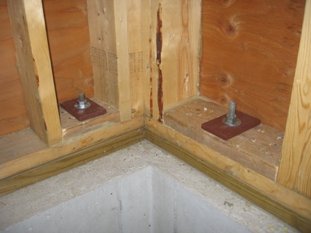 | Extra stiff bearing plates of mild steel were used (5" x 3" x ˝"), in conjunction with ⅝" all-threads, to tie down the structure to the foundation. By using multiple (stacked) sill plates, the wall sheathing can be used as collectors to transfer the loads from the studs to the sill plates. For this approach to work, the stacked sill plates must be designed to act as beams between the tie-down anchors. |
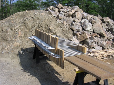 | The tie-downs were prefabricated. Nuts were installed at the dead ends, held in place by adhesive. A small plate could have been added, but given the 24" embedment, it was decided the nut alone would suffice. The wood blocks allowed for accurate placement on top of the forms. As the fresh concrete moved sideways in the forms, it forced some of the all-threads out of plumb. A wider, stiffer template should be used. Rods that were not plumb afterwards, were easily straightened with a piece of pipe. The PVC caps kept the threads clean during the pour. |
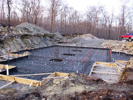 | The house sits on a 12" concrete slab, reinforced with # 5s at 12" in both directions. The slab was thickened underneath the columns and extends 12" past the basement walls. |
 | Door openings in the basement walls were carefully framed out and placed before the forms went up. All edges of openings were chamfered to avoid spalling. The basement is made of 4000 psi reinforced concrete and all beams, together with re-entrant corners were carefully reinforced to control cracking of the concrete. |
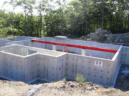 | The finished basement with two interior concrete columns for supporting the main steel beam (W12x26), continuous over three spans. The beam was primed and painted for corrosion protection. |
 | LVL beams (laminated veneer lumber) were used over large openings such as the garage doors. This door here is at the back of the garage. By extending beams past the sides of the openings, it was possible to achieve good portal frame action around the openings with the help of steel straps, as can be seen below. |
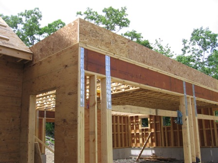 | Steel straps create moment connections between the narrow wall sections and the LVL beams above, giving this wall good transverse strength and stiffness (against racking). This can be repeated on the inside of the garage for even greater strength. Where the LVLs cross the interior supports, kick bracing may be needed to control the LVL compression "flange", depending on the span lengths. The top of the beam is fully braced by the floor and the designer must remember that this is not the case for the underside of the beam over the interior supports. |
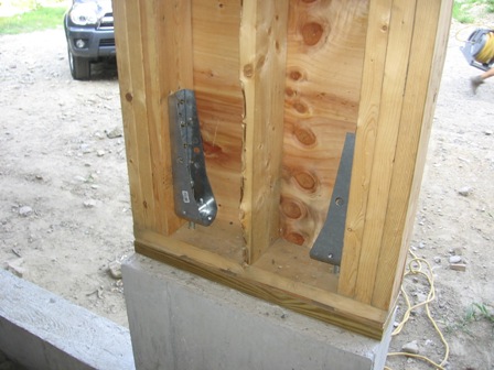 | The narrow wall sections between the garage doors were anchored down with (2) Simpson Strong-Tie connectors, giving each wall section a moment capacity at the bottom also. This second moment connection is not essential, but it helps to reduce deflections even further by increasing the in-plane stiffness of the wall. |
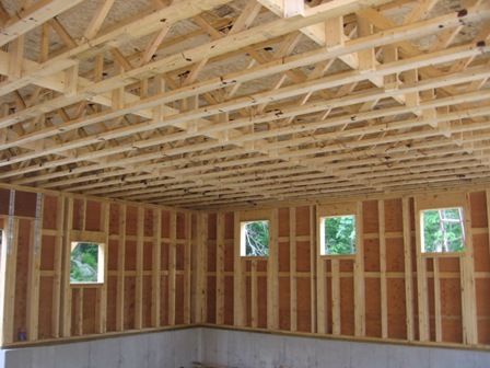 | The wall sheathing was 100% blocked for improved shear resistance. The floor trusses (Open Joist 2000) came with finger-jointed and glued connections. The truss-ends came fully blocked for vertical loading from the factory and can be cut to length on site. Trusses can be ordered in 1 ft increments and shortened by up to 11". Strong-backs (2x6) running through the trusses help to spread point loads to several trusses. The ľ" Advantech floor was glued and screwed, making for a stiff, composite floor.Open Joist 2000 |
| Middletown, Rhode Island | |
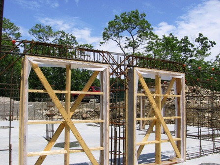
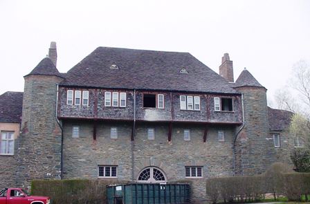 | For this private estate, CTE checked and engineered the roof structure for a change-of-use of the 3rd floor. Most interior support was removed and plywood shear walls were added to take the coastal wind loads. |
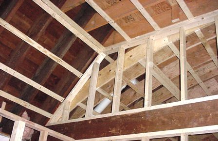 | The framing for one of the two shear walls that were added. The walls were anchored to a heavy, reinforced concrete floor. Computer modeling of the roof structure showed excessive sway in the roof framing due to a lack of stiffness, the result of the gutting of old interior walls and the raising of the rafter ties. |